If you work on a Toyota built between the mid-1980s and the early 2000s, such as a Corolla with a 4A-FE, a Camry with a 3S-FE or 5S-FE, a 22R-E pickup, a 1FZ-FE Land Cruiser or a 1UZ-FE Lexus, the engine is managed by TCCS, the Toyota Computer-Controlled System. Understanding how TCCS works is the fastest way to diagnose these engines correctly instead of replacing parts by guesswork.
This guide explains what TCCS controls, which sensors it relies on, how to read the old two-digit flash codes without a scan tool, what the ECU does when a sensor fails, and the basic checks to do before you condemn any component.
What is TCCS?
TCCS is Toyota’s name for computer control of the engine and, later, of other systems around it. At its heart is the Engine ECU (called the ECM in US terminology), a microcomputer that reads sensors and drives actuators many times per second.
Toyota’s first EFI computers for export models (from 1979) were analog circuits. Microcomputer control arrived in 1981, and that was the beginning of TCCS. Over the following years the same ECU took over more and more functions, and other systems (automatic transmission, ABS, traction control, suspension, air conditioning) received their own ECUs that exchange signals with the Engine ECU.
What the Engine ECU controls
| Function | What it does | Main inputs used |
|---|---|---|
| EFI – Electronic Fuel Injection | Calculates how long each injector opens, to keep the right air-fuel ratio | Air volume or manifold pressure, engine speed, coolant and intake air temperature, throttle position, oxygen sensor |
| ESA – Electronic Spark Advance | Sends the IGT signal to the igniter at the ideal moment | Crankshaft angle (G), engine speed (NE), load, coolant temperature, knock sensor |
| ISC – Idle Speed Control | Opens or closes an air bypass valve to hold a stable idle (cold start, A/C on, electrical load) | Engine speed, coolant temperature, A/C and neutral start signals |
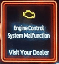
| Diagnosis | Detects faults, lights the CHECK ENGINE lamp and stores codes | All sensor circuits |
| Fail-safe and back-up | Keeps the car drivable when a sensor or the ECU itself fails | Built-in standard values |
Depending on the engine, the same ECU also controls auxiliary systems such as the overdrive cut-off, the oxygen sensor heater, EGR cut-off, A/C cut-off at full throttle, variable intake systems (ACIS, T-VIS) and turbo boost.
The sensors TCCS relies on
Most TCCS faults come from a sensor, its wiring or a bad ground, not from the ECU. Knowing the signal names used in Toyota wiring diagrams makes troubleshooting much easier:
- PIM – manifold pressure (vacuum) sensor: used on “D-type” EFI (for example the 4A-FE) to measure engine load.
- VS / KS / VG – air flow meter: used on “L-type” EFI. Older engines use a vane meter (VS), some use an optical Karman vortex meter (KS) and later engines a hot-wire mass air flow meter (VG).
- VTA / IDL – throttle position sensor: VTA is the throttle angle voltage; IDL tells the ECU the throttle is fully closed.
- G and NE – crankshaft/camshaft position: G gives the reference position, NE the engine speed. On older engines both pick-ups are inside the distributor.
- THW – coolant temperature sensor and THA – intake air temperature sensor.
- OX – oxygen sensor (or a lean mixture sensor on some lean-burn engines) for feedback control of the mixture.
- KNK – knock sensor: lets the ECU retard timing when knocking is detected.
- Switch signals: STA (starter), NSW (neutral start switch), A/C, electrical load, vehicle speed (SPD).
Most analog sensors are fed a regulated 5 V reference (VC) by the ECU and share the sensor ground E2. A broken VC or E2 wire can make several sensors appear faulty at the same time, so check them first when you get more than one sensor code.
Reading TCCS trouble codes without a scan tool
Pre-OBD-II Toyotas store two-digit codes that you can read by counting flashes of the CHECK ENGINE lamp. All you need is a short jumper wire (Toyota’s tool is SST 09843-18020).
Normal mode: step by step
- Check the conditions: battery at 11 V or more, transmission in N, all accessories off.
- Turn the ignition ON (engine off). The CHECK ENGINE lamp should light – if it does not, check the bulb and its circuit first.
- Bridge terminal TE1 (marked T on some models) to E1 in the check connector under the hood, or in the TDCL connector under the dash.
- Count the flashes:
- Steady blinking, about 2 times per second: no fault stored (“normal” code).
- Codes: the first digit flashes, a 1.5-second pause, then the second digit. A 2.5-second pause separates codes, and a 4.5-second pause marks the end of the cycle before it repeats. Codes are shown from the lowest to the highest number.
- Remove the jumper when you are done.
Tip: code 51 (switch condition signal) appears if the A/C is on, the accelerator is pressed or an automatic transmission is not in N. That is normal – correct the condition and read again.
Test mode: catching intermittent faults
Many TCCS engines with a TDCL also have a more sensitive test mode:
- With the ignition OFF, bridge TE2 to E1 (it will not enter test mode if you connect it with the ignition already on).
- Turn the ignition on: the lamp blinks quickly, which confirms test mode.
- Start the engine and drive while reproducing the customer’s complaint.
- After the road test, also bridge TE1 to E1 and read the codes as in normal mode.
Code 43 (starter signal) always appears in test mode if the engine was not cranked – ignore it in that case.
Common TCCS codes (example: 4A-FE)
| Code | System | What to check first |
|---|---|---|
| 12 | RPM signal (no NE or G signal) | Distributor pick-ups, NE/G wiring, starter signal circuit |
| 13 | RPM signal (NE lost at speed) | NE circuit, distributor connector, igniter |
| 14 | Ignition signal (no IGF) | Igniter, IGT/IGF wiring, ignition coil |
| 21 | Oxygen sensor / heater | Sensor heater circuit, sensor output stuck between 0.35 and 0.7 V |
| 22 | Coolant temperature sensor (THW) | Sensor, connector, open or short circuit |
| 24 | Intake air temperature sensor (THA) | Sensor, connector, open or short circuit |
| 25 | Air-fuel ratio lean | Vacuum leaks, fuel pressure, injectors, E1 ground, O2 sensor |
| 31 | Vacuum sensor (PIM) | Sensor hose, VC/E2 wiring, sensor |
| 41 | Throttle position sensor (VTA) | TPS adjustment, connector, wiring |
| 42 | Vehicle speed sensor | Speed sensor, speedometer drive, wiring |
| 43 | Starter signal | STA circuit, ignition switch, main relay |
| 51 | Switch condition signal | A/C, idle contact, gear lever position |
| 52 | Knock sensor | Knock sensor, its wiring and tightening |
Code meanings vary between engines and markets, so always confirm them in the repair manual for your engine. You can also search any code in our Toyota DTC code lookup.
Clearing TCCS codes
After the repair, clear the memory by removing the EFI or STOP fuse (15 A, depending on the model) for at least 10 seconds with the ignition off – longer in cold weather. Disconnecting the battery also works but erases the radio and clock settings. Then road-test the car and read the codes again: if the same code returns, the fault is not fixed.
Fail-safe and back-up: why the car still runs “badly”
TCCS is designed to keep the car drivable when something fails, which can hide the real problem:
- Coolant or intake air temperature sensor failure: the ECU substitutes fixed standard values, typically 80 °C (176 °F) for coolant and 20 °C (68 °F) for intake air. The engine runs but may be hard to start cold or run rich/lean.
- Vacuum sensor or air flow meter failure: the ECU uses fixed injection and timing values based on the idle contact, so the engine runs but with very poor performance.
- Knock sensor failure: timing is retarded to the maximum to protect the engine – the result is a noticeable loss of power and higher fuel consumption.
- No IGF (ignition confirmation) signal: fuel injection is cut to protect the catalytic converter from unburned fuel.
- Back-up mode: if the ECU’s microprocessor itself fails, a separate back-up circuit runs the engine with fixed injection and timing values and lights the CHECK ENGINE lamp – but no code is stored. A lamp that stays on with no code and very poor running points towards the ECU or its power and ground supply.
Basic inspection before replacing parts
When no code is stored (normal code), do these checks in order. Most drivability complaints on TCCS engines are found here:
- Battery voltage at 11 V or more with the engine stopped.
- Does the engine crank and start? If not, follow the no-start checks (fuel pump, circuit opening relay, spark, NE/G signals).
- Air filter: clean, dry and not oily.
- Intake air leaks: oil filler cap, dipstick, PCV hose, intake boots and vacuum hoses. Any leak after the air flow meter leans out the mixture.
- Idle speed: engine warm, accessories and A/C off, transmission in N. On a 4A-FE the specification is 800 rpm with the cooling fan off.
- Ignition timing: with TE1 bridged to E1, base timing on a 4A-FE is 10° BTDC at idle. After removing the jumper, check that the timing advances.
Values differ by engine – check the specification for your engine in the repair manual or our maintenance lookup. Never let a tachometer probe touch ground on the IG(–) terminal: it can damage the igniter or ignition coil.
Symptoms and where to look
| Symptom | Most likely causes |
|---|---|
| Hesitation on acceleration | Low fuel pressure, clogged filter, weak spark, vacuum sensor or TPS out of range, oxygen sensor |
| Backfiring or afterfiring | Leaking injectors, misfire, faulty temperature sensor, idle contact not closing |
| Lack of power | Fuel delivery, spark plugs, vacuum sensor, knock sensor fail-safe (timing retarded) |
| Stalls after starting | Circuit opening relay, injectors, cold start injector system |
| Stalls with A/C on or when shifting to D | ISC valve, A/C signal, neutral start switch signal |
When a fault only appears under certain conditions, try to reproduce it: tap or gently wiggle connectors (vibration), warm a sensor with a hair dryer (heat), spray water on the engine bay (humidity), or switch on all heavy electrical loads such as headlights, blower and rear defogger.
TCCS vs OBD-II
| TCCS (conventional OBD) | OBD-II | |
|---|---|---|
| Code format | 2 digits (e.g. 25, 31) | 5 characters (e.g. P0120) |
| Reading codes | Jumper TE1–E1, count lamp flashes | OBD-II scan tool on the 16-pin DLC3 |
| Clearing codes | Remove EFI/STOP fuse | Scan tool (or fuse) |
| Lamp after repair | Goes off after about 5 seconds | Goes off after 2–3 good drive cycles |
| Live data and freeze frame | Very limited | Full live data, freeze frame and active tests |
US and Canadian Toyotas switched to OBD-II around the 1996 model year, but many vehicles sold in other markets kept the two-digit flash-code system for several more years.
Frequently asked questions
Which Toyota engines use TCCS?
Most Toyota fuel-injected petrol engines from the mid-1980s to the late 1990s, including the A series (4A-FE, 4A-GE, 7A-FE), S series (3S-FE, 3S-GTE, 5S-FE), E series, R series (22R-E), RZ and TZ engines, the JZ, FZ and VZ engines and the 1MZ-FE and 1UZ-FE V6 and V8.
My CHECK ENGINE light is on but there is no code. Why?
If the engine runs very poorly at the same time, the ECU may be in back-up mode, which lights the lamp without storing a code. Check the ECU’s power supply (+B, BATT), its grounds (E1, E01, E02) and the ECU itself. Also remember that some codes only light the lamp in test mode.
Can I read TCCS codes with an OBD-II scanner?
No. Pre-OBD-II Toyotas do not use the standard OBD-II protocol, so a generic scanner cannot connect. Use the jumper method described above, or a Toyota-specific tester for older models.
Source: Toyota Motor Corporation, TCCS (Toyota Computer-Controlled System), New TEAM Step 3 Training Manual, Volume 1 (1997), based on the 4A-FE engine. This article summarises the main principles; specifications and code meanings differ by engine and market, so always follow the repair manual for the vehicle you are working on. See also our Toyota owner’s manuals and torque specifications.