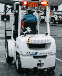
The Toyota 8FBN electric forklift (8FBN15, 16, 18, 20, 25 and 30) uses hydraulic drum brakes on the front wheels and a mechanical parking brake worked by a lever and cables. This page collects the brake service data from the Toyota 8FBN repair manual: drum and lining limits, spring lengths, pedal height and play, brake switch settings, parking brake force and bolt torques. For battery, fluids and general maintenance, see our Toyota 8FBN electric forklift guide.
In the tables, 1 t means the 1-ton series (8FBN15, 16, 18), 2 t the 2-ton series (8FBN20, 25) and 3 t the 8FBN30.
Brake system specifications
| Item | Specification |
|---|---|
| Service (foot) brake | Hydraulic, internal expanding, duo-servo, front wheels |
| Parking brake | Internal expanding, mechanical (lever and cables) |
| Master cylinder | Bore 19.05 mm, stroke 30 mm |
| Wheel cylinder bore | 1 t: 22.2 mm · 2–3 t: 28.5 mm |
| Lining | Resin mould, asbestos-free |
| Brake fluid | SAE J1703 / DOT 3 |
| Shoe adjustment | Automatic: the adjuster works when the brake is applied while reversing |
Brake drum and lining limits
| Item | Series | Standard | Limit |
|---|---|---|---|
| Drum inside diameter | 1 t | 254 mm (10.0 in) | 256 mm (10.1 in) |
| 2–3 t | 310 mm (12.2 in) | 312 mm (12.3 in) | |
| Lining thickness | 1 t | 4.9 mm (0.193 in) | 1.0 mm (0.039 in) |
| 2–3 t | 7.0 mm (0.276 in) | 2.0 mm (0.079 in) | |
| Wheel cylinder-to-piston clearance | 1 t | – | 0.125 mm (0.0049 in) |
| 2–3 t | – | 0.145 mm (0.0057 in) |
| Lining size (length × width × thickness) | Size |
|---|---|
| 1 t (8FBN15–18) | 279 × 48.5 × 5 mm |
| 2 t (8FBN20–25) | 323 × 60 × 7 mm |
| 3 t (8FBN30) | 343 × 60 × 7 mm |
Replace the shoes when the lining reaches the limit, and replace the drum if its inside diameter is beyond the limit or it is scored. Keep the lining and drum surface free of grease and oil.
Brake spring free lengths
| Spring | 1 t | 2–3 t |
|---|---|---|
| Shoe-to-anchor (return) spring | 102.2 mm | 106 mm |
| Strut-to-shoe spring | 19.7 mm | 23 mm (limit 20 mm) |
| Adjuster spring | 99.4 mm | 86 mm |
Unless a limit is given, replace a spring that is stretched so far that there is clearance between its coils when free.
Reassembly and brake set bolt torque
- Before fitting the drum, turn the adjusting screw so that the outside diameter of the shoes is about 1 mm (0.04 in) smaller than the drum inside diameter.
- Brake set (backing plate) bolts: 137–210 N·m (1,397–2,141 kgf·cm, 101–155 ft·lbf) on all series.
- The bolts need a thread-locking agent. Toyota specifies a different product according to the mark on the bolt head (no mark, A, B or C) – LOCTITE 201 or 204, or ThreeBond 2430 or 2471. Use the product given in the repair manual for each bolt, or fit new pre-coated bolts.
- After reassembly, bleed the brakes and check the braking force.
Braking force test and shoe adjustment
| Test (no load) | Standard |
|---|---|
| Braking distance from maximum speed | 5.0 m (16.4 ft) or less |
- Drive forward and in reverse several times, braking in reverse each time: the self-adjuster sets the shoe clearance automatically.
- If braking force is still too low, suspect a sticking adjuster, poor lining contact, oil or dirt on the lining, or a fluid leak. Remove the drum and inspect.
- After fitting new shoes, repeat forward and reverse travel with brake applications to bed in the linings.
Brake pedal height and play
| Item | Standard |
|---|---|
| Pedal height A (brake pedal bracket to top of pedal, with pad) | 144.5–149.5 mm (5.69–5.89 in) |
| Pedal play B – potentiometer type (8FBN15–30) | 11–15 mm (0.43–0.59 in) |
| Pedal play B – limit switch type (50-8FBN15, 18, 20) | 3–7 mm (0.12–0.28 in) |
Pedal height is set with the stopper bolt; pedal play is set at the master cylinder rod and lock nut.
Brake switch and stop lamp switch
The brake pedal sensor tells the controller when the brake is applied (for regenerative braking and the stop lamps). Two versions are used.
| Type | Adjustment | Screw torque |
|---|---|---|
| Potentiometer (8FBN15, 16, 18, 20, 25, 30) | Center the screw in the oblong hole, then move the sensor bracket until the PS1 output reads 1.1 ± 0.1 V on the display at the initial position (supply 5.0 ± 0.1 V). Connector pins: 5V, PS1, PS2, GND. | 1.57–2.35 N·m (16–24 kgf·cm) |
| Limit switch (50-8FBN15, 18, 20) | With no pedal play, the switch must turn ON when the pedal is pressed 3–10 mm. | 0.4–0.85 N·m (4.1–8.7 kgf·cm) |
| Stop lamp switch | Switch turns ON when pedal play is between 1 and 7 mm. | – |
Note: after replacing the potentiometer brake sensor, perform the sensor matching procedure with the display or service tool (repair manual section 13).
Parking brake
| Item | Standard |
|---|---|
| Lever travel | 38° to apply, 25° to release |
| Operating force (measured 24 mm from the top of the grip, lever moved 3–4 notches) | 177–216 N (18.1–22.0 kgf, 39.8–48.6 lbf) |
| Holding test | Truck must stay still with a load on a 15 % gradient |
- Adjust the operating force with the adjusting nut at the equalizer, then tighten the lock nut.
- Turn regenerative braking OFF before checking the parking brake force.
- To release, hold the release button and move the lever forward; it returns automatically. The parking brake lamp in the meter lights when the brake is applied (key ON).
Brake fluid
Use SAE J1703 / DOT 3 fluid and keep the level below the maximum mark on the reservoir. A falling level means worn linings or a leak at a wheel cylinder, line or the master cylinder. Toyota lists brake fluid replacement every 1,000 hours or 6 months (see the maintenance schedule in our 8FBN guide), and bleed the system after any hydraulic repair.
Steering data: the repair manual volume used here covers the drive unit, front axle, rear axle and brakes. Steering specifications are in the next volume and will be added when available.
Source: Toyota 8FBN15–30 forklift repair manual, section 6 (brake). Brakes are safety parts: work should be done by a qualified technician following the Toyota repair manual. See our Technical Disclaimer and the Toyota forklifts section. ToyotaSpace is not affiliated with Toyota Material Handling.